
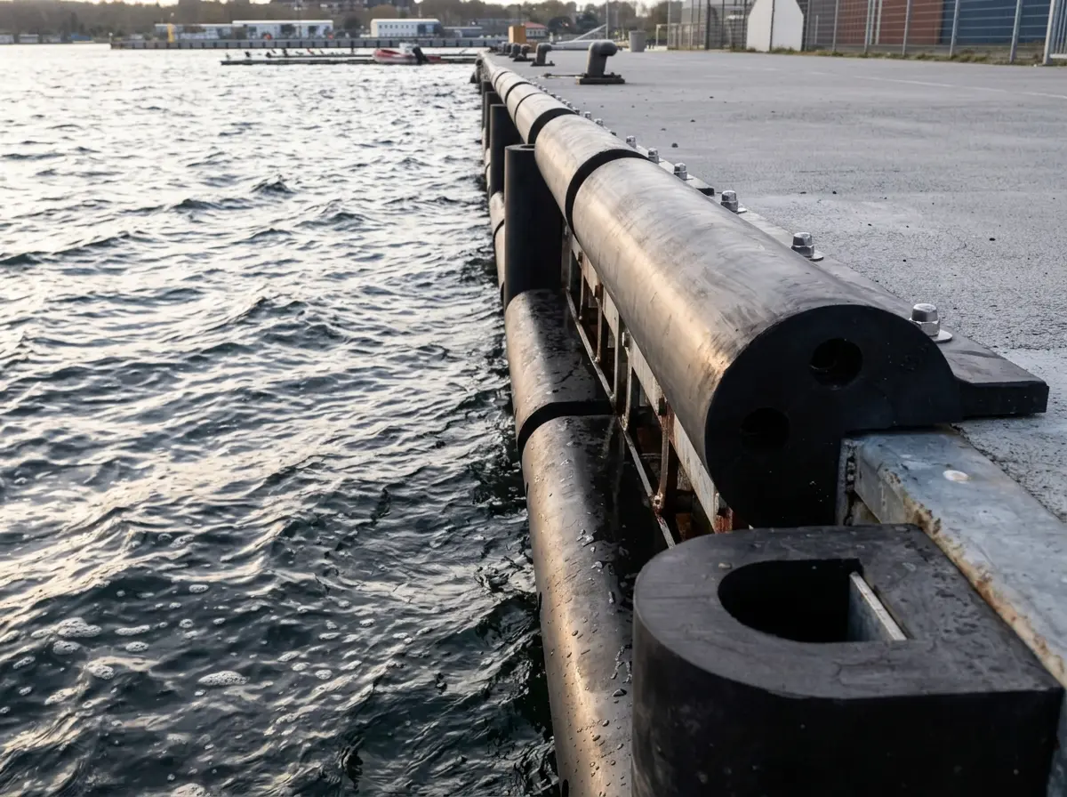
Choosing the right quay wall fender profile requires aligning a fender’s geometry, rubber formulation, and mounting geometry with the operational demands of incoming vessels and the structural limits of the berth. Effective marine rubber fender selection rests on two interdependent variables: total berthing energy absorption and peak reaction force tolerance.
This technical guide examines the core engineering criteria for marine fender selection, compares primary profile geometries—including D-type, cylindrical, corner, and square sections—and outlines key material and fabrication specifications that ensure long-term durability in marine environments.
Engineering Energy Absorption & Reaction Force
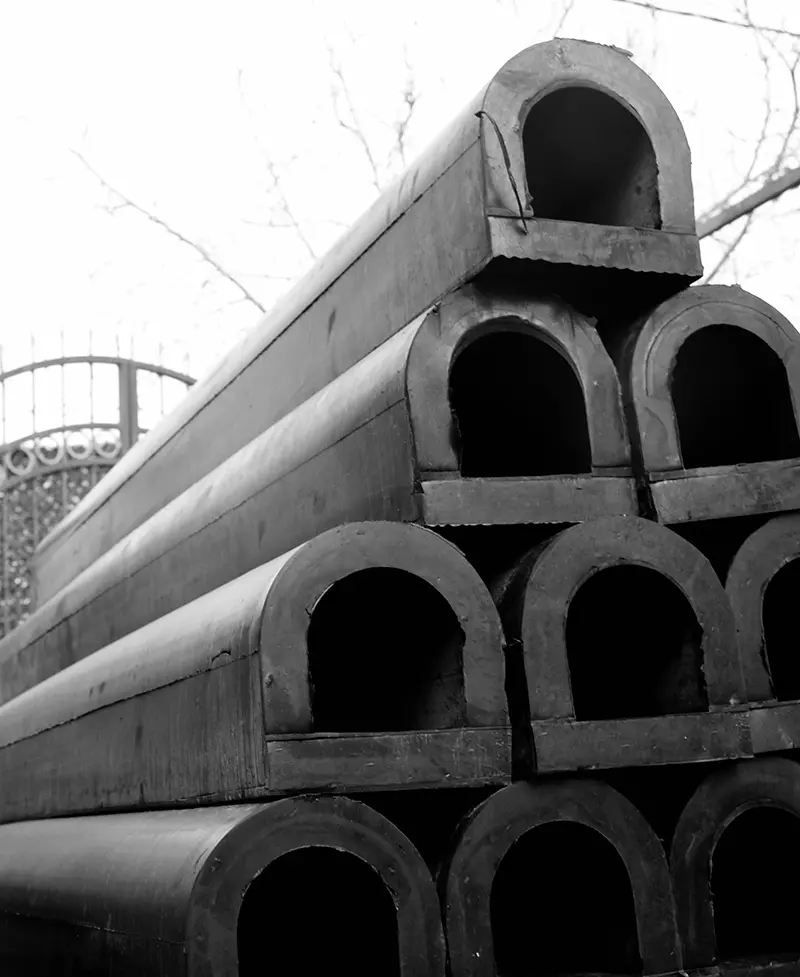
During berthing, a fender converts kinetic impact energy into elastic deformation. As the rubber compresses, it exerts a counter-force against the vessel hull—known as the reaction force. These two parameters operate in direct tension: designs configured for high energy absorption naturally generate higher reaction forces.
The primary goal of custom extruded rubber fender design is to absorb peak berthing energy while maintaining reaction forces safely below the maximum allowable stress limits of both the quay wall and the vessel hull plating.
Primary Calculation Inputs
Determining the required fender capacity begins with calculating total berthing energy. Key operational inputs include:
- Vessel Displacement: The maximum loaded mass of the target vessel.
- Approach Velocity: The vessel speed upon impact—the single most critical variable, as kinetic energy scales quadratically with speed.
- Berthing Angle: The contact orientation relative to the quay face, dictating point-load versus continuous-load distribution.
- Hydrodynamic Correction Factors: Added mass, eccentricity, berth configuration, and hull softness coefficients.
For commercial berths, fender reaction force calculations typically align with international standards such as PIANC guidelines to account for environmental exposure and tug-assisted maneuvering.
Evaluating Quay Wall Fender Profiles
Once energy and reaction targets are established, profile geometry dictates how the fender deforms and distributes loads under compression.
D-Type Rubber Fenders
Engineered with a flat square base and a hollow D-shaped inner chamber, D-type rubber fenders deform in a controlled, progressive manner. The broad base provides high mounting stability against continuous quay faces, making them an industry standard for berths, jetties, and wharves accommodating small to medium displacement vessels.
Cylindrical Fenders
Featuring a symmetric round cross-section, cylindrical fenders absorb impact uniformly from virtually any approach angle. Their reaction force builds linearly as compression increases. This multi-directional response makes cylindrical profiles ideal for berths experiencing heavy rolling motion, varying freeboard heights, or significant tidal fluctuations.
D-Type vs Cylindrical Rubber Fenders
Choosing between these two classic profiles comes down to berth geometry and motion dynamics. D-type fenders offer a low-profile, highly stable barrier along flat concrete walls where impact direction is predictable. Conversely, cylindrical fenders provide greater shear tolerance and accommodate irregular contact points, such as those encountered by tugs, workboats, and barges.
Corner Type Fenders
Unprotected 90° masonry edges represent the highest risk areas for concrete spalling and hull damage. Corner type fenders deliver dedicated dock corner bumper protection, absorbing both head-on bow impacts and lateral shear forces at exposed marina edges and quay corners.
Square & Rectangular Fenders
With high cross-sectional mass and low deflection rates, square and rectangular profiles act as rigid, heavy-duty impact barriers. They are widely specified for industrial loading bays, transport ramps, and heavy-tonnage workboat berths where frequent, severe contact is expected.
Material Formulations & Fabrication Tolerances
Geometrical performance must be backed by high-grade elastomer compounding to prevent premature fatigue, ozone degradation, and mechanical tearing.
Elastomer Selection
- Natural Rubber (NR): Delivers exceptional elasticity, high tensile strength, and superior structural recovery under repeated cyclic loads.
- SBR Compounds: Offers strong mechanical resistance to abrasion and tearing, serving as a reliable standard for general commercial harbour use.
- EPDM Formulations: Provides maximum resistance to weathering, direct UV exposure, and thermal oxidation in exposed coastal environments.
Environmental Stability & Pre-Drilling Specs
High-performance marine compounds maintain mechanical integrity across broad operating temperatures from -30°C to +110°C and pass strict ozone crack testing under ISO 1431-1 Method A. They also resist deterioration from saltwater exposure and oily harbour waters.
To streamline jobsite installation, factory pre-drilling should be specified directly to project blueprints. Standard configurations typically incorporate Ø50 mm countersunk upper mounting holes for flush hardware placement alongside Ø26 mm lower passage holes, both held to precision tolerances of ±1 mm. Custom length cutting (CST) further eliminates the need for field trimming.
Rubber Fender Mounting Options & Installation Best Practices
Even a correctly sized fender system will underperform if mounting arrangements fail under shear stress or corrosion. Key fixing considerations include:
- Recommended Bolt Spacing: Anchors must follow engineered spacing layouts to distribute load evenly along the profile length.
- Flush Countersunk Fixing: Mounting bolt heads must sit fully recessed within upper countersunk holes to prevent direct contact with vessel hulls.
- Precision Mitred Joints: Factory-cut 45° corner joints ensure seamless, continuous protection around masonry turns without leaving exposed gaps.
- Corrosion-Resistant Hardware: Fixing kits should utilize marine-grade stainless steel or hot-dip galvanized steel components to maximize service life.
Maintenance & Technical Specification Support
Systematic inspection ensures fender lines maintain rated energy absorption over their design life. Maintenance teams should regularly inspect profiles for surface cracking, permanent compression set, or localized tearing, while checking anchor bolts for torque loss and joint alignment.
Matching the ideal quay wall fender profiles to your facility starts with analyzing vessel displacement, berth exposure, and structural load capacity. Early collaboration between project engineers and rubber manufacturers allows compound hardness, profile geometry, and fixing details to be tailored precisely to site conditions. Rubbersan’s technical engineering team reviews berth requirements to provide optimized profile recommendations, compound selections, and custom fabrication specifications for any marine project.